How can we generate signals?#
Voltage levels and TTL#
Receiving signals from devices#
Impedance and current sinking/sourcing
Logic levels and tolerances
Implementation with Arduino#
Creating simple logic with Arduino#
counting frames
If you want to provide stimuli at specific interval or specific frames of the acquisition, you can either pre-program serier of triggers to camera and stimuli apparatus; or you can count frames (using Exposure signal from camera) and perform stimulation trigger at specific counts, e.g. every 100 frames. This can be implemented using simple Arduino code for almost any imaging system that provides Exposure signal (camera-based and point-scanning system as well, see example from ScanImage software)
when X, do Y
Continuous monitoring of input signal allows triggering at precise moments in time. One example is detecting when signal crosses level for frame acquisition, such as piezo position above certain level if we want to acquire image only at a specific height of the objective.
driving LEDs
Advanced details#
Interrupts
There are two main ways to detect incoming signal: continuous polling of the pin and using interrupts.
// using polling:
void loop(void){
  if(digitalRead(pin) == HIGH){
    // do stuff
  }
}

// using interrupts:
void setup(void){
  pinMode(interruptPin, INPUT_PULLUP);
  attachInterrupt(digitalPinToInterrupt(interruptPin), isr, RISING)
}

void isr() {
  // do stuff
}
Digital-to-analog converters
Many Arduino devices come with Analog-to-digital converters on-board that allow reading analog values from pin, but not digital-to-analog converters that allow generating arbitrary continuous signals, e.g. for setting LED brightness or moving stages or galvos. DAC devices are separate cards that communicate with Arduino code via specific protocols. Another use for DAC is offset and scaling, for example when we want to translate one signal into another while performing simple (or not) arithmetics. In light sheet microscopy we often want to synchronize position of galvos (that define position of light sheet) with position of piezo collar (that defines position of objective and focal plane). However, the signals are often not compatible directly, e.g.
galvo_voltage = (piezo_voltage + offset)*factor
One can use integrated scaling amplifier to do that math, or employ DAQ (such as Arduino code).
int outputVal = 0;
int inputVal = 0;
int inputPin = A0;

// these factors will relay input voltage to output voltage without modification

float offset = 0;
float scale = 4095/1023;

void loop(){
  inputVal = analogRead(inputPin); // can be 0-1023 that corresponds to 0-5V
  outputVal = (inputVal - offset) * scale;
  dac.setVoltage(outputVal, false); // can be 0-4095 that corresponds to 0-5V
}
Real-time data processing
As discussed in the Devices can’t follow signals perfectly section, devices don’t perfectly replicate control signals. Similarly, microcontrollers, DAQs, and computers don’t output perfect signals with perfect timing. We call these non-real-time systems, meaning that processing power can be taken over by different process. This causes jitter in timing of signals, or even missed signals all together. Arduino controller is close to real-time device when we are interested in <1kHz signals. Computers (PCs) are generally not real-time because operating system can be “taken over” by different process.
Serial port communications
Arduino digital pins can be used for fast communication using binary signals: LED can be either on or off; camera exposure can happen or not. Serial communication using ASCII commands allows for easier control of parameters or passing of messages between Arduino and PC or between Arduino and other devices supporting serial communication. One problem we had to solve is playback of sounds from PC every 100 frames. To solve that we were using frame counting (discussed above) and send serial command to PC program that was listening to Arduino communications. Then PC program (written in Python) would output specific sound through on-board speaker. Using this approach we avoided integrating hardware for sound playback directly into Arduino.
Interfacing with PC by emulating keyboard
When creating user-facing controls for custom hardware, we often need to create physical buttons that control software running on PC. For example, buttons to move Z stage, joystick to move XY stage, buttons to perform acquisition Software often has API that can be used to integrate external device. Micro-Manager microscope control software allows users to write plugins that can be connected with external Arduino device via serial commands. However, sometimes it is easier to program external device as a keyboard to execute hotkey commands on demand. For example, see how Arduino can be wired to perform arbitrary hotkey command when a certain pushbutton is pressed.
DAQ (NI DAQs)#
More advanced technology for generating fast, predictable signals with option for feedback loops is using Data Acquisition (DAQ) platform such as National Instrument devices (currently “gold standard”) or very similar Advantech iDAQ (at lower price point). Here we discuss several specific example of using DAQ for driving microscope operations.
Function/Waveform generators#
Function generators (waveform generators) are specialized devices that output high-quality signals with high sampling frequency but only specific waveform. While DAQ device can produce any arbitrary shape of signal, e.g. squared sine wave multiplied by triangle wave of different frequency, function generators offer limited variety of output functions. As it commonly happens, the tradeoff is speed vs customization.
You can buy 30MHz two-channel function generator for $300, while multi-functional DAQ with 2 analog output channels and 2MHz sampling rate can cost more than $2000. There are stand-alone waveform generators as well as cards that need PC-based programming (same as DAQs).
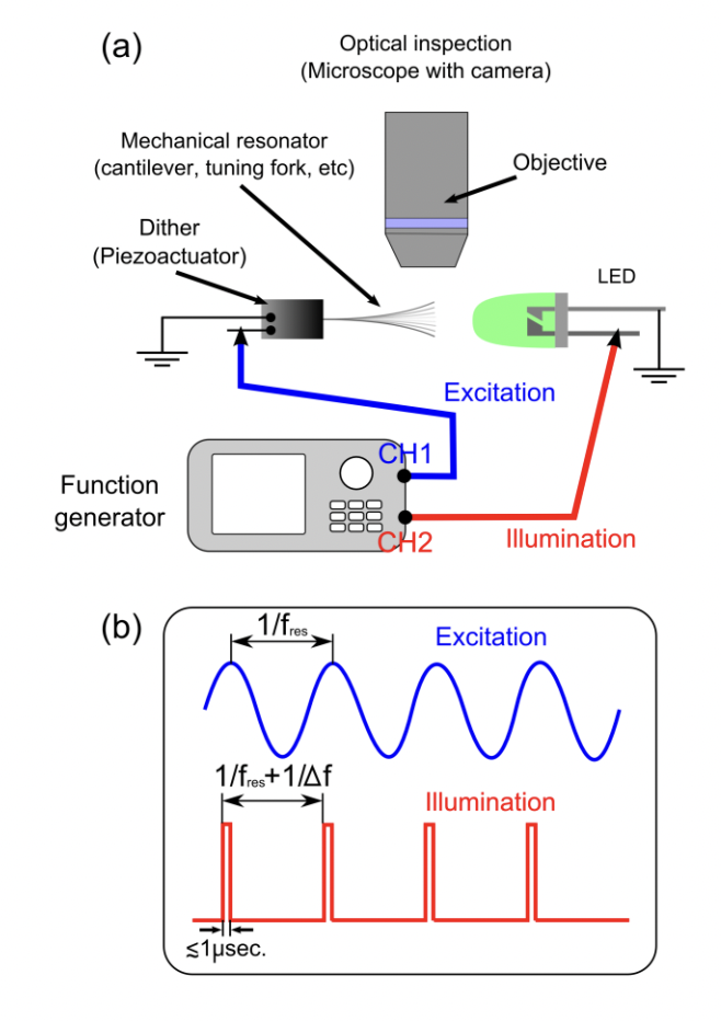
Using two- or four-channel generators allows synchronization of signals and phase offset, e.g. if you want one signals to be precisely 0.15ms ahead of another signal or with a precise frequency difference.
For example, here author is using 2-ch function generator to drive piezo (sine wave) and strobing LED (square pulses) with slightly different frequency to analyze resonant frequency of piezo actuator:
Sensors: temperature, humidity, flow, light#
When running experiments we often need to record additional information such as temperature, light level, or humidity. Some external devices offer logging capabilities, but it might be also useful to construct custom device to record such data directly from the sensor. For example, Arduino can be used to log (as well as control) temperature.
In such case the simple setup looks like this:
sensor reports data to Arduino, for example digital DS18b20 sensor can report temperature through “1-wire” protocol
Arduino sends the data via serial port to python script running on PC
script writes the data in text file appending timestamp information
Off-the-self devices such as Thorlabs USB temperature logger provide similar capability without any tinkering but at ~3x price