Making devices talk to each other#
Microscopes are complex systems with significant electro-mechanical features and separate parts need to communicate with each other.
Cameras, stages, light sources, and other devices need to be activated or switched from one mode to another at an appropriate time, for example to achieve multi-color imaging or time-locked stimulation in animal experiments. Devices can receive and send signals digital and analog signals. Digital
Digital signals#
signals are sent using voltage levels: for example, if voltage is 5V it is considered “HIGH” or “1”. In practice, devices can define “HIGH” as voltage between 2V and 5V, and “LOW” or zero as voltage between 0V and 0.8V. If voltage is between 0.8V and 2V then the signal is “undefined” and the device might or might not perform triggered action.
Consider camera example. Modern scientific cameras provide GPIO (general-purposes input/output) interface in a single Hirose-type connector:
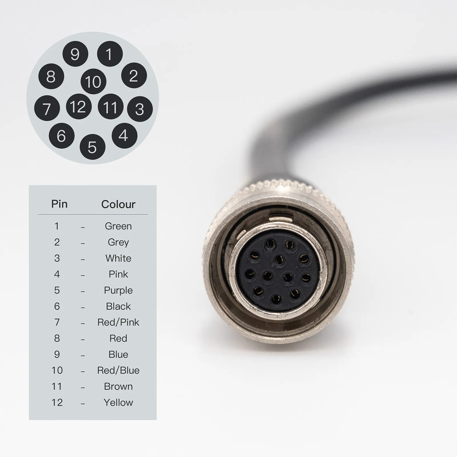
Pins on the connector are providing different signals: ground voltage, input (hardware trigger), output (exposure) or other signals. For example, if voltage between ground pin and input trigger pin reaches “HIGH” level, then the camera will perform exposure. Each cables has different correspondence between pin number and color of individual wires. Depending on the software setting of the camera, the exposure duration will be defined from user interface or will last as long as the voltage is “HIGH”.
Other examples of devices control by digital signals include shutters (1=open, 0=closed) and LED light sources (1=on, 0=off).
Analog signals#
Analog signals are used when control variable is not binary. For example, we might want to control laser power, which can be any number between 0% and 100%. In such cases devices are driven by modulation signal, which can be defined as voltage between 0V and 5V, however some devices are driven by 0…2V or even -10V…10V signal range - always check the specification. Apart from laser power, another examples of analog control signals are position of stage (e.g. piezo collar), LED light intensity, galvo mirror angle
When using amplitude modulation to drive devices, one has to remember that:
the input signal might not be linearly correlated with output values (e.g. LED brightness is non-linear function of input voltage; )
the non-linear behavior of system can make response slower or shifted in time
Analog signals are produced by Digital-to-Analog converters (ADC) that have specific amplitude resolution (it can’t output any arbitrary voltage only one number of 1024 for 10-bit or 65536 for 16-bit resolution)
Devices often output driving signal as a feedback. For example, you can send trigger signal to camera and readout exposure signal that provides timing of when actual image was taken. Piezo might output signal corresponding to physical position of stage (readout by a separate sensor on the device). It might be useful to examine what device is actually doing compared what you tell it to do.